Impulse Responses
Interpreting impulse responses is an important part of acoustic analysis. An impulse response measurement can tell us a great deal about a room and the way sound will be reproduced within it. It can show us what kinds of treatment will be helpful and whether treatments have been correctly applied to achieve the best results. This page explains impulse responses, the information that can be extracted from them and how REW can measure and analyse such responses.
What is an impulse response?
Before we can get very far in interpreting an impulse response we need to understand what an impulse response is. The impulse response is in essence a recording of what it would sound like in the room if you played an extremely loud, extremely short click - something like the crack of a pistol shot. The reason for measuring the impulse response (by more subtle means than firing a gun in the room) is that it completely characterises the behaviour of the system consisting of the speaker(s) that were measured and the room they are in, at the point where the measurement microphone is placed. An important property of an impulse, not intuitively obvious, is that it if you break it up into individual sine waves you find that it contains all frequencies at the same amplitude. Strange but true. This means that you can work out a system's frequency response by determining the frequency components that make up its impulse response. REW does this by Fourier Transforming the impulse response, which in essence breaks it up into its individual frequency components. The plot of the magnitude of each of those frequency components is the system's frequency response.
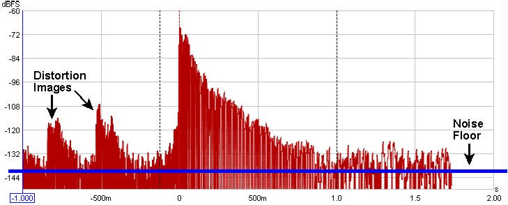
When an impulse response is measured by means of a logarithmically swept sine wave, the room's linear response is conveniently separated from its non-linear response. The portion of the response before the initial peak at time=0 is actually due to the system's distortion - looking closely, there are scaled down, horizontally compressed copies of the main impulse response there - each of those copies is due to a distortion harmonic, first the 2nd harmonic, then the third, then the fourth etc. as time gets more negative. The initial peak and its subsequent decay after time=0 is the system's response without the distortion.
In a perfect system of infinite bandwidth with totally absorbent boundaries, the impulse response would look like a single spike at time 0 and nothing anywhere else - the closest you get to that is measuring the soundcard's loopback response. In a real system, finite bandwidth spreads out the response (dramatically so when measuring a subwoofer as its bandwidth is very limited). Reflections from the room's boundaries add to the initial response at times that correspond to how much further they had to travel to reach the microphone - for example, if the microphone were 10 feet from the speaker and a sound reflection from a wall had to travel 15 feet to reach the microphone, that reflection would contribute a spike (smeared out depending on the nature of the reflection) about 5 ms after the initial peak, because sound takes about 5 ms to travel that extra 5 feet.
When measuring full range responses from loudspeakers (rather than subwoofer responses) the reflections are easier to spot as the higher bandwidth of the full range system keeps the spike of the impulse (and the reflections) quite narrow, but you need to zoom in on the time axis to see them. They are easier to spot with a linear Y axis (set to %FS instead of dBFS) and also show up more readily with the ETC smoothing set to 0.
Impulse Response Windows
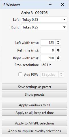
After capturing a sweep, FFT processing is carried out to derive the system's impulse response and the corresponding frequency response. There are controls to adjust the position and widths of left and right windows that define the portion used to derive the frequency response, these controls may be accessed by pressing the "IR Windows" button on the toolbar.

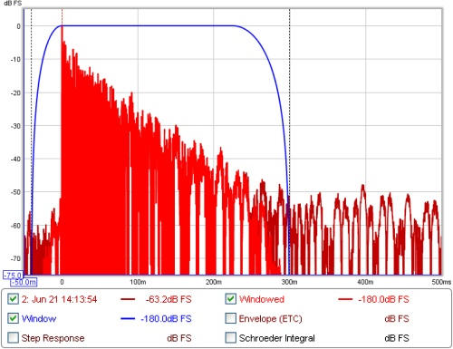
The windows and the region of the impulse response they cover can be viewed on the Impulse graph by selecting the "Window" and "Windowed" traces. The reference position for the windows is usually the impulse peak
The default settings for the windows will usually be suitable. In smaller rooms it may be necessary to use a shorter right-side window duration, around 300-500ms - if the frequency response plot appears noisy and jagged try reducing the right window period and hit "Apply Windows" to recalculate the frequency response. In very large rooms the window can be increased to improve the frequency resolution.
The frequency resolution corresponding to the current total window duration (left and right combined) is shown above the Apply Windows button - the longer the duration, the higher the resolution. Alternative window shapes may be selected independently for the left and right windows.
In addition to the left and right windows a frequency-dependent Gaussian window can be applied. This is a window whose width varies inversely with frequency, getting progressively narrower as frequency increases. The width of the window can be specified as a number of cycles or an octave fraction. If the width is in cycles then the width (between the half amplitude points of the window) at any frequency will be the number of cycles times the period of that frequency, for example a 15 cycle window will have a width at 1 kHz of 15 * (1/1000) = 0.015 s or 15 ms. The corresponding octave fraction has an effect similar to applying a smoothing of the same octave fraction, except the variable window excludes progressively more of the late arriving sound as frequency increases rather than just averaging it out - this has similarities with the way the ear increasingly picks out the direct sound from the speaker at higher frequencies.
If Add frequency dependent window is selected the frequency dependent window is applied after first applying the selected left and right windows. The FDW is centred on the window reference time - for best results this should be at the peak of the impulse.