Minimum Phase
In discussions of equalisation, and particularly equalisation applied to attempt to improve the acoustic response in a room, "minimum phase" will often crop up - generally in the context of whether or not EQ can successfully be used to address a response problem. So what is "minimum phase", and why should we care?
There are rigourous mathematical and systems theory definitions of what constitutes a minimum phase system, but I will not repeat them here. In the context of acoustic measurements a system which is minimum phase has two important properties: it has the lowest time delay for signals passing through it and it can be inverted.
Minimum Phase and Time delay
The "lowest time delay" property refers to the amount the frequency components of a signal are delayed while delivering the measured frequency (SPL) response. We can see the delay characteristics directly in the Group Delay plot of the system. Given a measured frequency response we cannot tell from the SPL response alone whether what we measured has this "minimum delay" characteristic. If there was a time delay in the overall system somewhere, such as the time taken for sound to travel from the loudspeaker to the microphone, that delay would render the system non-minimum phase (in the strictest sense of the term) but would not alter the SPL response we measured.
A time delay causes a phase shift that increases with frequency - for example, a delay of just 1ms results in a phase shift of 36 degrees at 100Hz but 3,600 degrees at 10kHz, because 1ms is 1/10th of the 10ms period of a 100Hz signal but is 10 times the 0.1ms period of a 10kHz signal, and each period is 360 degrees. The phase shift caused by a time delay is linear with frequency, meaning the 1ms example would give 36 degrees of phase shift at 100Hz, and twice that delay at twice the frequency or three times the delay at three times the frequency etc. If the frequency axis is set to linear the phase plot of a time delay looks like a straight line droppping down as frequency increases - how steeply it drops depends on how large the delay is.
Whilst constant time delays make it difficult to interpret the phase response, they can be removed from our measurements and they do not cause any problems with applying EQ. However, just removing time delays (or their effects) is not enough to make a system minimum phase, there is more to it than that.
Minimum Phase and Invertibility
Minimum phase systems can be inverted, which means that a filter can be designed that, if applied to the system, would produce a flat response and correct the phase response at the same time. That is clearly a nice property to find if we want to apply EQ. If we apply EQ to a system that is not minimum phase, or more particularly in a region where it is not minimum phase, the EQ will not produce the results we would like. It may still be possible to achieve a flat response, but correcting the phase response would elude us. It is simply not possible.
A simple example of something that renders a response non-minimum phase is reflections that are as large or larger than the direct signal (reflections along paths that are different but the same length can combine to produce higher levels, or a curved surface can focus a reflection). In the simple case of a reflection that is exactly the same amplitude as the direct signal, we would find there were regularly spaced frequencies at which the reflection is 180 degrees out of phase with the direct sound. When those signals combine, the result is zero amplitude at those frequencies (an extreme example of the comb filtering often seen in acoustic measurements). That zero level cannot be restored to what it should have been by any amount of EQ, as the EQ affects the direct and reflected signals equally so the signals still cancel. If a response has regions in it that are zero it cannot be inverted and it is not minimum phase. If the reflection is larger than the direct sound the problem is equally tricky, as although we no longer have a zero level we would end up with a situation where the corrections the EQ is applying would have to keep getting larger to counter the ever larger reflection and we would quickly run out of headroom.
Identifying Minimum Phase Regions
Room responses are mixed phase, meaning there are some minimum phase regions and some regions that are not minimum phase. The minimum phase regions tend to be at lower frequencies, but we cannot simply say a response is minimum phase below some specific cutoff. It is not possible to identify minimum phase regions from looking at the wrapped phase response, especially if the measurement has any time delay. The unwrapped response gives some more clues, plotted against a linear frequency axis, but often covers such a huge span that it is impractical to use. Even if we remove any time delay in the measurement the phase response alone still doesn't let us easily identify the minimum phase regions. There is a straightforward method, however. Here is a measurement of a sub+main speaker in-room:
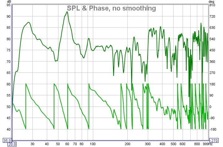
We might hazard a guess that this is largely minimum phase below the room's transition frequency, and non-minimum phase above, but to avoid the guesswork we can look at group delay. The group delay plot shows us how much each frequency is being delayed - mathematically, it is the slope of the unwrapped phase plot, so anywhere that phase is dropping linearly corresponds to a constant group delay region (i.e. that region is delayed by a constant time). Here is the group delay plot for the measurement:
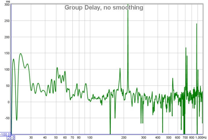
That gets us a bit closer, we can speculate that the places where there are particularly wild swings in group delay are not minimum phase, but it still doesn't let us easily identify the minimum phase regions. To do that, we need to compare the measurement with a system that has the same amplitude response but is minimum phase and look at the measurement's excess group delay. The minimum phase response is generated by using the measurement amplitude and calculating the corresponding minimum phase from it, using a mathematical relationship between the two that holds for minimum phase systems. By looking at the difference between the measured and minimum phase (the excess phase) and measuring the slope of that difference to find the excess group delay, we get this plot:
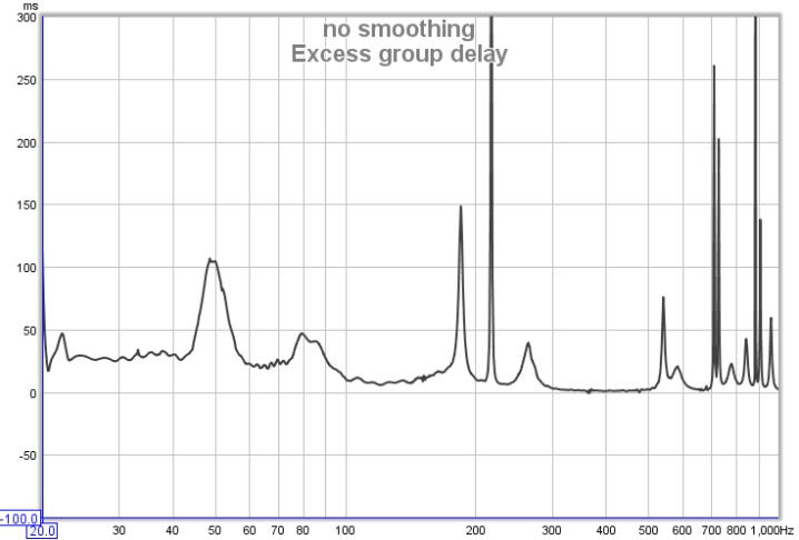
Now we have something we can work with. Anywhere the excess group delay plot is flat is a minimum phase region of the response. We can see there are regions even at very low frequencies where the response is not minimum phase, between about 44 and 56Hz for example. These will usually correspond to regions where there are sharp dips in the response, and underline the poor results which are often found when trying to lift such regions with EQ. Low frequency peaks on the other hand are usually in minimum phase regions, the plot is fairly flat in the region of the 28Hz and 60Hz peaks, which bodes well for attempts to apply EQ to them. In general, the peaks in a response are a result of features that are correctible through equalisation (speaking technically, they are due to the poles of the response and the equaliser can place zeroes that cancel the poles).
There are regions at relatively high frequencies which are minimum phase, such as 300 to 500Hz, despite the wild variations of the response in that area, so it would be possible to apply EQ there. However, we need to remember that the measurement is only valid for the microphone location at which it was made, and as frequency increases the response changes more rapidly as the microphone moves. EQ that looks good at the original measurement position may give worse results at other positions, so it is important to check wherever listeners will be. Narrow bandwidth EQ adjustments should not be used outside the modal range, the higher the frequency the broader the EQ adjustment needs to be to stand any chance of being useful outside a very small region.
As an aside, the excess group delay plot also clearly shows there is a time offset between the subwoofer and the main speaker, the sub being about 25ms delayed, which is not so obvious from the overall group delay plot. Excess group delay is a useful plot for time aligning speakers.
A common cause of non-minimum phase behaviour in rooms
If minimum phase systems are cascaded (connected in series) the overall system remains minimum phase - the individual transfer functions of the systems are multiplied together and this retains the minimum phase characteristics. In terms of the paragraph about invertibility above, the minimum phase systems will not have zero amplitude anywhere and multiplying non-zero values together will not generate a zero value. However, adding the responses of minimum phase systems gives a result which is typically not minimum phase throughout its response. If there are any areas where the responses of the systems we are adding are equal in magnitude but opposite in phase, their sum will be zero. Here we see the problem for room responses, because the room response we measure is the summation of many different responses due to the sound radiating into the room and reflecting from its surfaces. This also applies even at the lowest frequencies, as we can see in the following.
Axial modes in a rectangular room
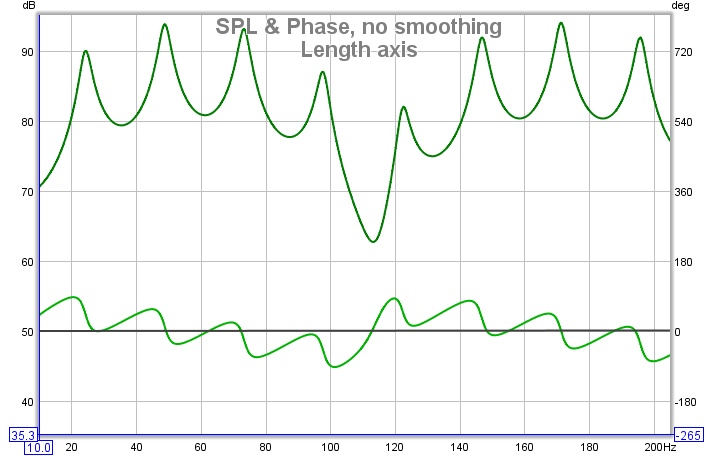
To provide a simple example of how the summation of the signals in a room can make it non-minimum phase, even at low frequencies, we can look at the behaviour of axial modes in a perfectly rectangular room. Such results are easily simulated (in this case by REW's own simple modal simulation tool), giving us a well controlled set of responses to study. For the responses below the room dimensions are 7.00 x 6.86 x 3.43m, giving length modes every 24.5Hz, width modes every 25Hz and height modes every 50Hz. The source is against the front wall, 0.25m from the left wall and 0.15m from the floor. The mic is 1.5m from the rear wall, 4.28m from the left wall and 1m from the floor. The room surfaces have uniform absorption of 0.20 at all frequencies.
The first plots show the individual SPL and phase responses of each axis. All are perfectly minimum phase, so the excess phase (the black line) is flat and remains at zero. A linear frequency axis is used to more easily see the modal effects, which are linearly distributed in frequency.
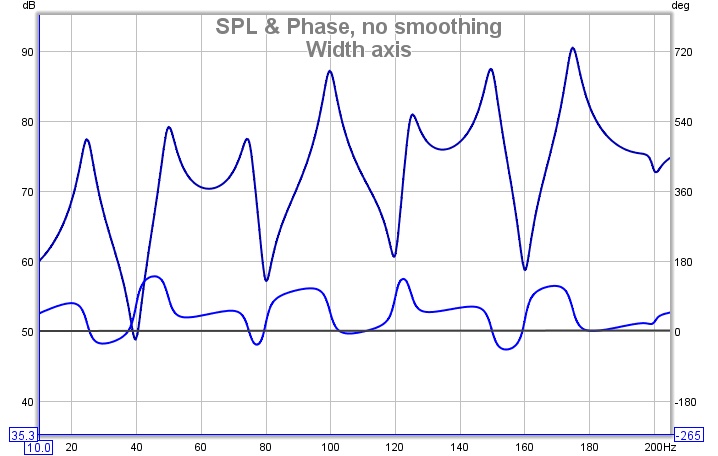
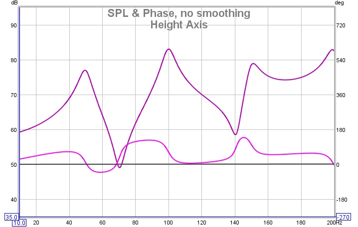
Now for the combined response, which shows the minimum phase in grey and the excess in black, followed by the excess group delay plot:
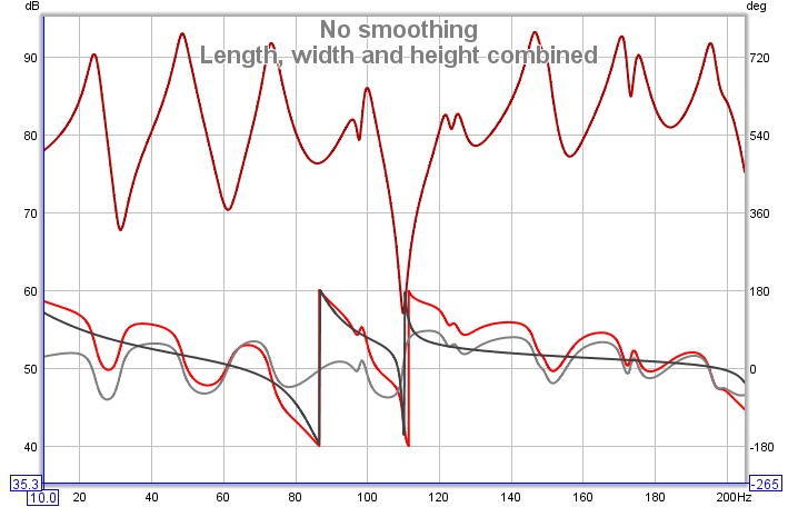
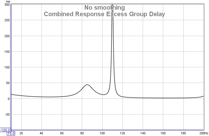
The response is no longer completely minimum phase anywhere in the span, as we can see from the excess phase, but it deviates dramatically in the 70-120Hz region. At 110Hz, where there is a sharp dip in the response, there is a sharp peak in the excess group delay. Attempting to EQ the response to flat in this region would be foolish. Regions where the response is far from minimum phase would typically not give the results we might expect and they are best left alone from an EQ perspective. Non-minimum phase regions are also likely to show greater variation with position and to be more affected by changes within the room, as a change that affects any of the signals that sum to the response in the minimum phase region can greatly alter the behaviour there. On the plus side, broadband acoustic treatments in the room are effective regardless of the room's minimum or non-minimum phase behaviour.
Note that the predicted EQ results REW shows in its EQ window are obtained by applying the chosen filters to the measured impulse response, and include the effects of non-minimum phase behaviour, so they accurately portray the results that would be obtained at the point the measurement was taken.