Making Measurements
Once the audio input and output have been chosen, the interface has been calibrated, the levels have been checked and the SPL reading has been calibrated REW is ready to make response measurements.
Connections should be as explained in Getting Started, if connected to an AV processor, select the input to which the interface's output is connected.
Making a Measurement
- Press the Measure button
 (or Ctrl+M) to bring up the Measurement dialog
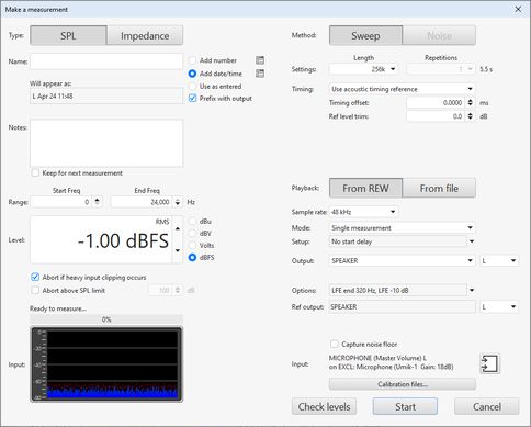
- Make sure the SPL/Impedance selector at the top of the Measurement panel is set to SPL (see Impedance Measurement for information about measuring impedance)
- Enter a name for your measurement. REW can prefix the measurement name with the output channel and/or automatically append a number or the date and/or time to the name according to the selections to the right of the name. To use just a number or just a date or time leave the name blank and select the desired option. The name that will be used is shown below the name you enter, the buttons to the right of the naming options provide further settings. Notes for the measurement can be entered in the box. The name and notes can be changed afterwards in the Measurements Panel

- Set the Start Freq to the lowest frequency for which you wish to see the response and End Freq to the highest. The sweep will span the range from half the start frequency to twice the end frequency (with an overall limit of half the interface sample rate) to provide accurate measurement over the selected range. A different end frequency can be applied when measuring the LFE channel, see the Output options below.
- Level controls the rms signal level at which the sweep is generated. The maximum value is -3 dBFS or its equivalent in dBu, dBV or volts, unless the View preference Full scale sine rms is 0 dBFS has been selected, in which case the maximum is 0 dBFS. Using the maximum value places the peaks of the signal at digital full scale. The default value is -12 dBFS. This control is normally preset to the Sweep Level established during the Check Levels process. If you will be comparing measurements from several speakers, or comparing a series of measurements from a speaker, make sure they are measured with the same Sweep Level. An automatic 10 dB reduction in level can be applied when measuring the LFE channel to allow for the 10 dB gain the processor or receiver applies, see the Output options below.
- There are two protection mechanisms for sweep measurements. Abort if heavy input clipping occurs will abort the measurement if more than 30% of the samples in an input block are clipped. Abort above SPL limit will abort the measurement if the SPL exceeds the limit that has been set. Note that if the limit set is higher than the input can measure before clipping occurs it will not offer any protection, but in that case the first mechanism might be triggered.
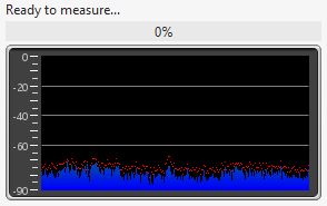
- Measurement progress and input levels are shown below the Level control.
- Settings for the measurement method are on the right hand side. Length controls the length of the sweep, specifying the number of samples in the sequence. The default is 256k which works well for most purposes. Dividing the number of samples by the interface's sample rate gives the sweep duration in seconds, shown to the right. The overall duration includes silent periods before and after the sweep.
If the input and output are on the same device and so share a common clock longer sweeps will provide higher signal-to-noise ratio (S/N) in the measurements. Long sweeps may be problematic when the input and output are on different devices, such as when using a USB mic, as their sample clock rates will differ. Over a long sweep a significant difference in clock rates could cause severe distortions in the shape of the impulse response and affect the phase response. This can be corrected by using the acoustic timing reference and the Analysis option to Adjust clock with acoustic ref or, if a loopback connection is being used as a timing reference, the Analysis option to Adjust clock with loopback.
Each doubling of the sweep length improves S/N by almost 3 dB. However, the time required to perform the processing after each sweep will more than double. If REW is running on a computer which does not have a fast processor and a lot of memory, measurements will be much faster using a shorter sweep at a small S/N penalty of about 3 dB for each halving of the length. At least 4 GB of RAM and a fast processor are recommended if using the 1M sweep, at least 8 GB for the 4M sweep. Invalid measurements or out-of-memory errors may occur on computers which have insufficient RAM or processor speed.
Warning: REW's longer sweeps are provided to facilitate high signal-to-noise ratio measurements of electronic equipment, particularly at high sample rates. If they were used with loudspeakers the risk of overheating the tweeter would increase with the sweep length, great care would be needed to avoid high SPL and ensure the signal remained within the tweeter's power handling capability. Using long sweeps for loudspeaker measurement is not recommended. - REW allows multiple sweeps to be averaged, although best results are generally obtained by using single, longer sweeps rather than multiple, shorter sweeps. Multiple sweeps are offered when not using a Timing reference or when using a loopback as a timing reference. Do not use multiple sweeps if the input and output are on different devices (for example, if the input is a USB mic). If Repetitions is more than 1 REW uses synchronous pre-averaging, capturing the selected number of sweeps per measurement and averaging the results to reduce the effects of noise and interference. The pre-averaging can improve S/N by almost 3 dB for each doubling of the number of sweeps. Averaging can be useful if the measurements are contaminated by interference tones, whether electrical or acoustic, as they typically will not add coherently in the averaging and hence will be suppressed by the process.
Warning: some interfaces do not maintain sample synchronisation between the successive sweeps which produces a corrupt measurement that has multiple, closely-spaced peaks of approximately the same level in its impulse response, 1 peak for each sweep. This can also happen if the input and output are on separate devices. If the frequency response with multiple sweeps is significantly different from the response with a single sweep, stick with single sweeps - A Timing reference can be selected for the measurement, see Measuring with a timing reference for more on the settings when using a timing reference. When not using a timing reference there are 3 choices for the t=0 position of the measured impulse response: (1) Set t=0 at IR peak will place t=0 at the exact position of the peak of the IR, determined by interpolating an oversampled version of the IR; (2) Set t=0 at IR start will place the t=0 point at the sample before the IR first exceeds 10% of the peak level; (3) Set t=0 from delay estimate will use cross-correlation with a minimum phase version of the impulse to estimate and remove any time delay.
- Playback selects whether the sweep is played by REW or will be played back from a Measurement Sweep file that has been generated and saved previously from the signal generator. Usually REW plays the sweeps, see Measuring with file playback for more on using a file.
- The Sample rate is selected below the Playback control.
- SPL measurements have a Mode selection which can be Single measurement, Repeated measurements or Sequential channels.
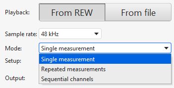
- There is a Setup button below the mode selection which brings up a list of settings to apply
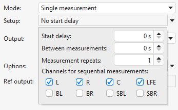
Those include a start delay before the measurement starts, a delay to use between repeated or sequential measurements, the number of repetitions for repeated measurements and the channels to measure for sequential measurements. The Start delay control can be used to provide time to move away before the measurement starts. - Single measurement is commonly used. Repeated measurements allows a series of measurements to be made without further intervention by setting the total number required in the Measurement repeats count. That may be useful when making a series of polar measurements, using the Between measurements delay control to specify how long REW will wait before starting each sweep to allow time to reposition a speaker turntable, for example.
- The Sequential channels mode allows each selected channel to be measured in turn without further intervention. If those channels include the LFE output the Output options below have settings that can be for the LFE only.
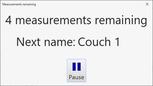
- When making repeated or sequential measurements a panel is shown with the number of measurements remaining, the name that will be assigned to the next measurement and a pause button that will stop the sequence when the current measurement completes and continue it when un-paused.
- The Output for single and repeated measurements is selected below the Playback control. If a timing reference is being used the Ref output and Ref input may also be configured.
- The output Options button brings up a list of output-related settings.
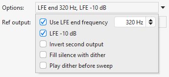
If Use LFE end frequency is selected the end frequency figure alongside will be used when measuring the LFE channel. REW detects the LFE channel by the channel label for Java drivers, for ASIO drivers it looks for an output name that contains "LFE" and if there isn't one it assume channel 4 is the LFE. If LFE -10 dB is selected an automatic 10 dB reduction in sweep level is applied when measuring the LFE channel to allow for the 10 dB gain the processor or receiver applies. - If two outputs are being driven the Invert second output box controls whether the second output gets the same signal as the first or an inverted signal. An inverted signal might be used when driving a balanced input or using REW's Virtual balanced input option.
- If Fill silence with dither is selected the generator will replace silent parts of the sweep with 16-bit dither. This option is provided to try and counter aggressive output muting which some DACs exhibit when one of their input channels does not have any signal. There is some penalty in the impulse response noise level, though it is far below the noise floor for acoustic measurements, only potentially having an impact when measuring electronics. Nonetheless the option should only be selected if required to counter device behaviour.
- If Play dither before sweep is selected the generator will play a short period of dithered silence before the sweep starts. This option is provided to ensure the replay chain is active before the sweep signal starts.
- The input will be as set up on the Soundcard preferences, the current selection is shown with a button alongside that brings up a dialog to change the input and related options.

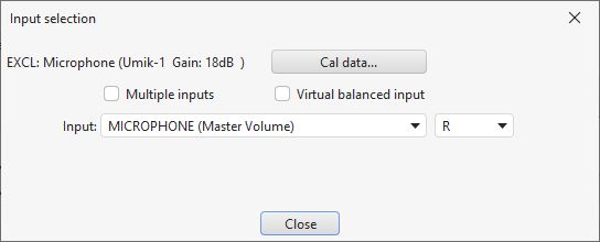
- If a Multiple input measurement is being made there is a Configure average... button on the input selection dialog to select whether the individual inputs are weighted and/or have their SPL aligned before the average is calculated. There is also an option to create a Virtual balanced input by subtracting a second input from the measurement input.
- The Calibration files... button shows a dialog that lists the calibration files for the current input and output.
- The Check Levels button generates a few seconds of a pink noise signal that depends on the frequency range selected for measurement and checks that the input level is not too high or too low. Pressing Cancel while the pink noise signal is playing will turn it off (it turns off automatically after 3 seconds). The rms level that was measured is shown on the measurement panel, with a warning if the level is too high or too low
- Press Start to make a measurement. If a delay has been configured the time remaining before the sweep begins is shown
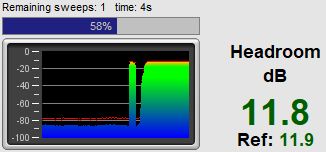
- When the sweep starts progress is shown on the measurement panel along with a display of the measurement headroom and, if a timing reference is being used, the headroom for the reference
The result of the measurement is displayed in the graph area, information about the measurement appears in the Measurements Panel. The measurement name can be changed if desired by entering a new name in the box at the top of the measurement panel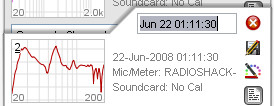
Notes relating to each measurement can be entered in the notes area, click the Notes button ![]() if the notes area is not visible
if the notes area is not visible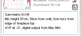
For details of the various ways of viewing the measured data, including averaging multiple measurements, refer to the Graph Panel help.
Measurement Headroom
The headroom figure on the measurement panel shows how far away the input is from clipping, and hence how much the sweep level could be increased before clipping would occur. The figure is red if there is less than 6dB of headroom (warning that the input is close to clipping), green between 6 and 40 dB (or between 6 and 60 dB for USB mics). A message is shown if the headroom is more than desirable, as increasing the Sweep Level or the AV processor volume would improve the signal-to-noise ratio in the measurement which in turn increases the accuracy of the impulse and frequency responses. Note that after making such a change subsequent measurements will be at a higher SPL on the graphs than those made before the change.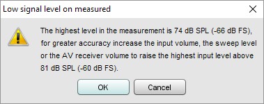
If the room's resonances are very large the input signal level may exceed the input range and cause clipping. If this occurs a warning is displayed, as input clipping will cause errors in the derived frequency response. The sweep level, AV processor volume or input volume should be reduced and the measurement repeated. Note that after making the change subsequent measurements will be at a lower SPL on the graphs than those made before the change.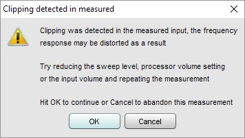
If the signal levels are very low this may indicate a connection problem: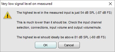
After measuring the response of a channel you can look at adjusting EQ immediately, or make other measurements first.
Note that some resonances which are very pronounced when measuring a speaker alone do not appear if a pair of speakers (e.g. Left and Right) are run together - this is because the positioning of the speakers in the room can prevent some resonances being excited (in particular, the odd order width modes will not be excited by content which is the same on Left and Right speakers if they are symmetrically placed across the width). Such resonances can often be left uncorrected, to identify them compare measurements from individual channels with those made with two channels driven at the same time (achieved on AV32R DP or AV192R by setting the entry in the TMREQ filter menu to Yes and selecting the channel which is to repeat the test signal, or on other processors by connecting both left and right interface outputs to the selected AV processor input or using a Y lead to drive two inputs at once).
Measuring with a timing reference
REW can make use of a timing reference when it measures, according to the setting on the measurement panel. The timing reference selection controls whether REW uses a loopback on the interface as a timing reference, or an acoustic timing reference, or no reference. Using a timing reference allows REW to eliminate the variable propagation delays within the computer and interface so that separate measurements have the same absolute timing.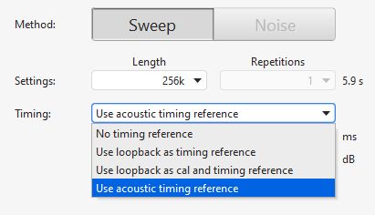
Timing offset
A Timing offset can be set that will shift the response relative to the timing reference, allowing the time of flight delay to be removed if using a loopback connection, for example. The timing offset can be set manually or from the figure calculated using the Estimate IR Delay function.
If a loopback is selected the reference channel signal must be looped back from output to input on the interface and measurements will be relative to the loopback timing. Usually this means measurements will have a time delay that corresponds to the time it takes sound to travel from the speaker being measured to the microphone, which can be removed for subsequent measurements using the Timing offset.
Loopback timing reference
There are two loopback options, using the loopback for timing only (Use loopback as timing reference) or using the loopback for both timing and to compensate for the loopback path frequency response Use loopback as cal and timing reference. If the loopback is used to compensate for the loopback path frequency response there are two options. The first is Merge loopback response into IR, which subtracts the loopback path frequency response from the measured response and produces a corresponding impulse response. That works well for full range measurements (sweeps from 0 Hz to half the sample rate) but may have artefacts in the IR if used with sweeps over a limited frequency range. The second is Make calibration data from loopback response, which generates a soundcard calibration data entry for the measurement based on the frequency response measured on the loopback input. In both cases the loopback level at 1 kHz is used to define a 0 dB reference, subject to a check that the loopback response is not more than 20 dB higher than the 1 kHz level anywhere. If that is the case it is offset so that the maximum level (and hence the maximum that will be subtracted from the measurement input response) is 20 dB. If 1 kHz is not within the span of the measurement a frequency in the middle of the measurement span (in a log sense) is used. The distortion results for the measurement input use the response before applying loopback response corrections as the fundamental, otherwise relative distortion figures would be incorrect. Note that using the Use loopback as cal and timing reference option instead of using a soundcard calibration file generated from the measurement input may introduce errors at the frequency extremes where the channel match can degrade.
Acoustic timing reference
If an acoustic timing reference is used REW will generate a timing signal on the output that has been selected to act as the reference before it generates measurement sweeps on the channels being measured. The timing signal is a sweep from 5 kHz to 20 kHz lasting about 700 ms. It must be directed to a speaker that can reproduce high frequencies, one that has a tweeter. The level of the timing signal is set relative to the measurement level using the Ref level trim control, it may need to be higher or lower depending on whether the speaker used as the timing reference is further away or closer than the speaker being measured. The timing signal is a high frequency sweep to allow accurate timing, a subwoofer cannot be used as the reference channel. Measurements will have a time delay that corresponds to the difference in their distance from the microphone compared to the distance of the reference speaker - if the reference speaker is further away the delay would be negative. The delay can be shifted using the Timing offset. When an acoustic timing reference is used individual measurements taken from the same mic position will have the same relative timing, allowing trace arithmetic to be carried out on the traces in the All SPL graph. Note that multiple sweeps cannot be used when using an acoustic timing reference.
System delay
If using a timing reference REW can calculate the delay through the system being measured relative to the reference and show it in the measurement Info panel as System Delay in milliseconds, with the equivalent distance in feet and metres shown in brackets. Any Timing offset is shown below the System Delay. For speakers the delay estimate is based on the location of the peak of the impulse response. Subwoofers have a broad peak and a delayed response due to their limited bandwidth so the delay is instead measured relative to the start of the impulse response. The start of the impulse response cannot be located as precisely as the peak, however, so delay values are less accurate for subwoofer measurements.
Measuring with file playback
It sometimes is not possible to connect to an input on the system being measured for it to play back the sweep. If the system can play back from files a sweep file can be used instead.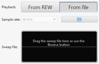
A Measurement Sweep file must be generated and saved from the REW signal generator. The sweep file must include the acoustic timing reference signal, REW uses that to synchronise input capture to playback on the system being measured. A copy of the file is placed on the system being measured and the file is also loaded into REW so that it can configure the correct measurement frequency range, sweep settings and sample rate, which are retrieved from the file.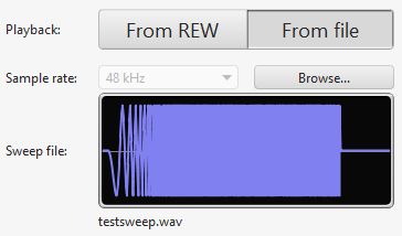
There are two options for timing reference when measuring with a file, acoustic and wired. When using the acoustic timing reference REW listens for the timing signal on the measurement input, where it will be picked up by the mic. That may not be suitable when measuring with direct connections to the outputs of a system that requires file playback as the timing reference must always be on the output being measured. In those cases the wired option allows a different input channel to be assigned for the timing signal, separating timing detection from measurement.
After loading the file and selecting the appropriate timing reference configuration press Start, REW will then capture the noise floor and pause, showing Waiting for timing reference...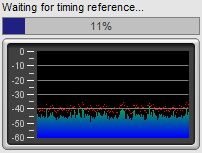
Now play back the file on the system being measured, once REW detects the timing reference it will capture the sweep and generate the measurement.
Number of measurements
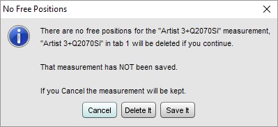
REW can have up to 199 measurements loaded at once according the setting for Maximum measurements in the View preferences, the default is 30. If the maximum number has been reached when a new measurement is requested a warning is given as the first measurement would need to be removed to make room for the new one: